Radial Cutting Logic for Free Membrane Edges
A case study from textile architecture practice
In textile architecture, some of the most important design questions do not arise from form alone, but from the translation of form into a reliable fabrication logic. This becomes particularly evident when an existing membrane structure must be reconstructed without dependable documentation and adapted to changed boundary conditions.
A recent replacement study for the funnel-shaped canopy in the courtyard of Rapperswil Castle presented exactly such a condition. The project showed that radial panel layouts are not simply a geometric preference, but in some cases a structural and fabrication necessity. It also demonstrated how parametric modelling can support reverse engineering and help establish a robust intermediate geometry for later cutting-pattern development.
Project context
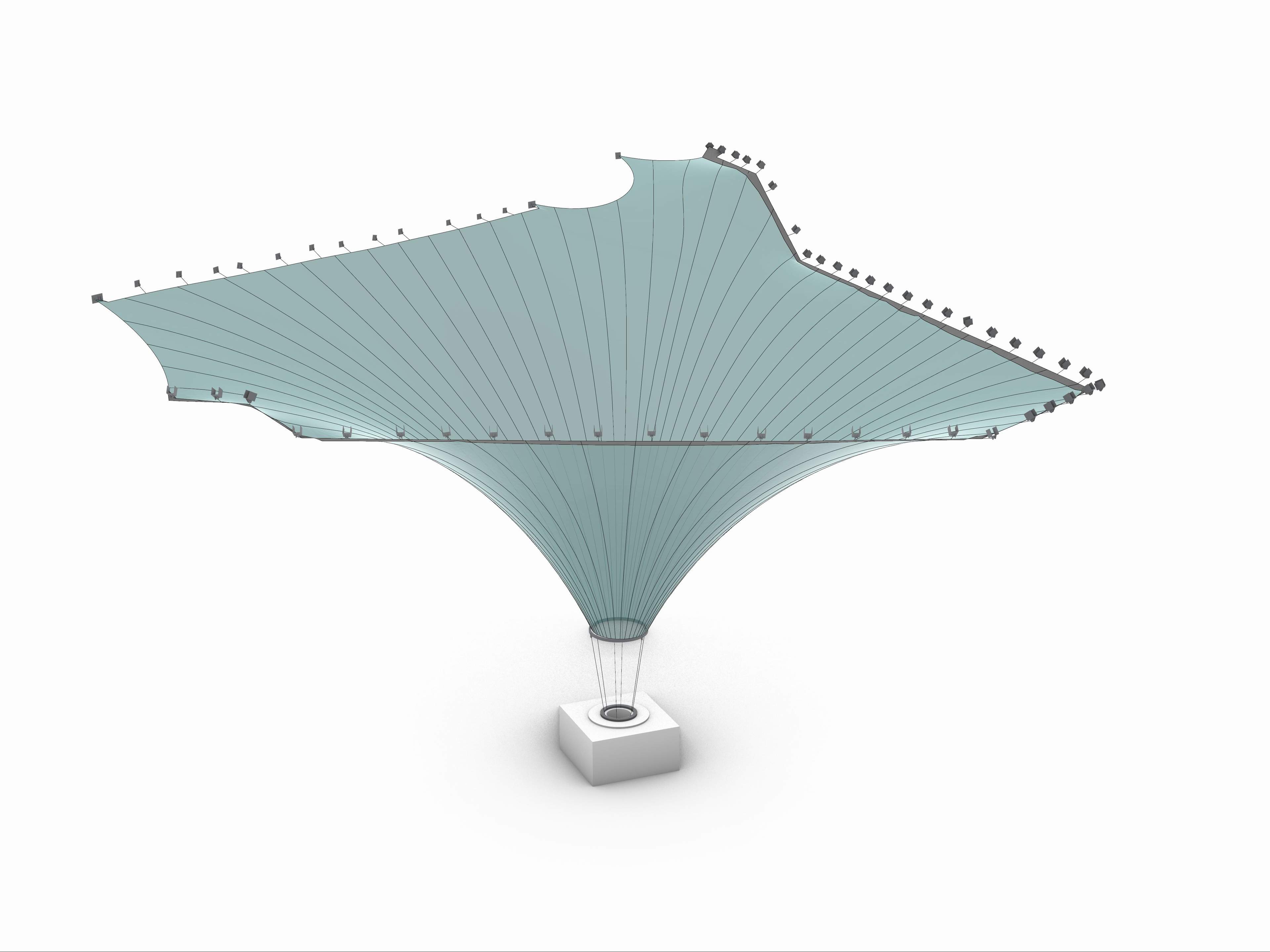
The courtyard canopy at Rapperswil Castle was erected in 2007 as a temporary textile structure. It provides seasonal weather protection so that the courtyard can function as a sheltered event space, while the roof is dismantled during the cold season.
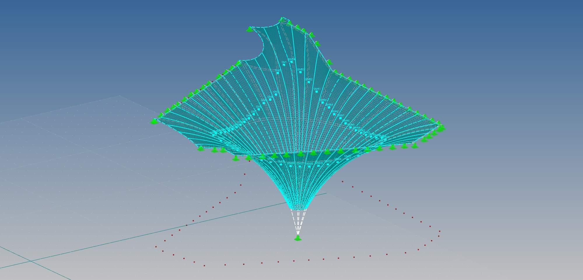
The structure is substantial in scale. Its plan area is 378 m², while the effective roof surface reaches 455 m². The funnel-shaped canopy rises to a height of 12 m and spans approximately 22 × 27 m. The primary material consists of transparent PVC foil, reinforced with PVC-PES straps.
After nearly two decades of repeated assembly and dismantling, the membrane has reached the end of its service life. Although it has withstood numerous storms, it has also suffered from long-term handling and seasonal use. In addition, alterations to the site required the relocation of the lower tension ring, meaning that the original geometry could no longer be assumed to remain valid.
Because no reliable design records were available, the replacement process had to begin with reverse engineering. This was necessary not only to recover the geometry of the existing roof, but also to incorporate the geometric changes resulting from later construction work.
Why panel layout became the key issue
At first glance, a conical or funnel-shaped membrane may appear to be primarily a form-finding problem. In this case, however, the more critical question was how to derive a fabrication-ready panel layout from the reconstructed geometry.
The canopy is governed by orthotropic material behaviour, which makes a radial panel layout necessary. This is a key distinction. In textile construction, one must differentiate between cartesian panel arrangements and radial or polar panel arrangements. Cartesian layouts may be appropriate for translational or orthogonally organised surfaces, but membranes structured around an internal high or low point require a fundamentally different logic. Funnel-shaped canopies are a typical example.
The practical challenge in Rapperswil was intensified by the available base material. The PVC foil could only be obtained in rolls with a width of 1.4 m. For a roof of this scale, using such a narrow material economically requires a carefully developed panel layout. A purely intuitive or visually convenient subdivision would inevitably lead to excessive seams, inefficient strip widths, and an unstable cutting strategy.
Form-finding and radial material logic
Another relevant aspect of the case is that the original form-finding did not rely on a force-based approach, but on a projection-based method. For steep conical membranes, this is a technically coherent choice. Such geometries do not behave like point-supported saddles or simple orthogonal membrane fields. Their logic is radial, and their stress state cannot be understood independently of this radial organisation.
This is particularly important when material directions are aligned radially. In such cases, geometry, material orientation, and later cutting logic are closely interrelated. The panel layout therefore cannot be treated as a secondary drafting task. It becomes part of the structural reading of the surface.
Why equal angular division is not enough
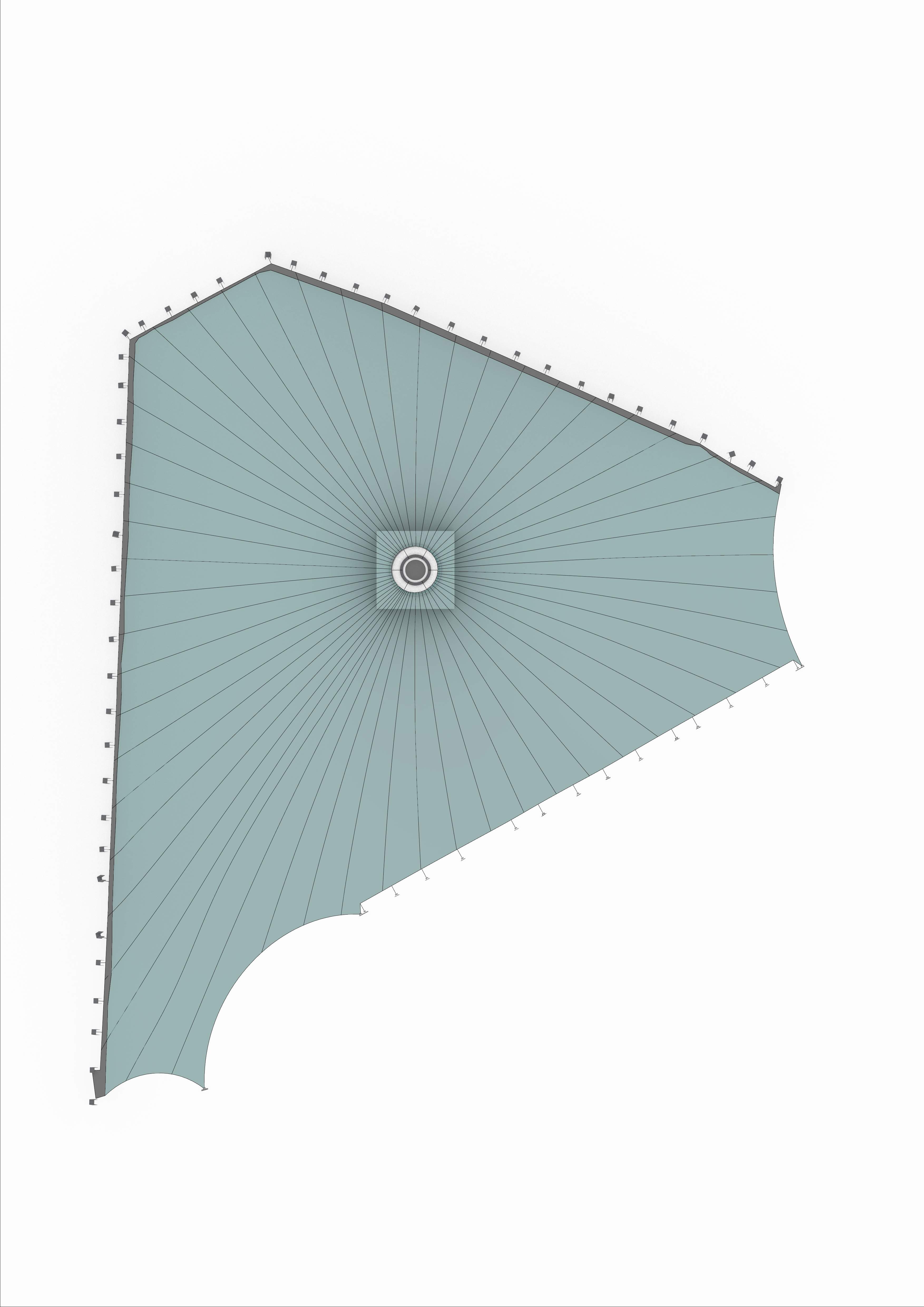
Once a radial panel layout is required, the next question appears straightforward: why not simply divide the membrane from the centre using equal angles?
For free boundaries, this does not work satisfactorily.
If radial lines are distributed with constant angular spacing, the resulting strip widths at the perimeter vary significantly. Wherever the boundary lies further away from the internal reference point, the resulting segment becomes wider. Wherever the radius is shorter, the segment becomes narrower. The geometry may still look orderly, but the resulting fabrication logic is inconsistent.
For a large membrane made from a narrow base material, this inconsistency has direct consequences. It affects the number of welded seams, the practicality of the panel widths, the material yield, and ultimately the economic feasibility of production.
The task, then, is not simply to subdivide a free contour radially, but to do so in a way that produces a balanced and fabrication-oriented distribution of strip widths.
A parametric helper geometry
This is where a parametric workflow became useful. The aim was not to generate the final cutting lines directly, but to establish a helper geometry that could structure the membrane in a controlled and reproducible way.
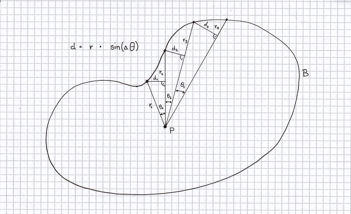
The basic setup is conceptually simple:
a closed boundary curve,
an internal reference point,
and a set of radial construction lines extending from that point to the boundary.
The difficulty lies in the distribution of those lines. Their density must respond to the actual geometry of the boundary. Where the distance to the boundary increases, the angular spacing must decrease. Where the distance becomes smaller, the angular spacing can increase. In other words, the radial logic must follow a direction-dependent distance field, not a schematic angular grid.
This helper geometry does not define the final cutting pattern. Its role is to generate control points and a stable topological structure that can support the next stages of the workflow.
Why Grasshopper was useful
This kind of problem can be addressed effectively in Grasshopper, not because the software itself is the topic, but because the problem is inherently parametric.
The workflow involves reading and reconstructing a free boundary, defining an internal reference point, generating radial test lines, detecting their intersection with the boundary, evaluating directional distances, and using those values to derive a more balanced radial subdivision.
These relationships become highly transparent in a parametric environment. Geometry, parameters, and evaluation criteria can be adjusted interactively, which is particularly valuable when working with imperfect or reconstructed source geometry.

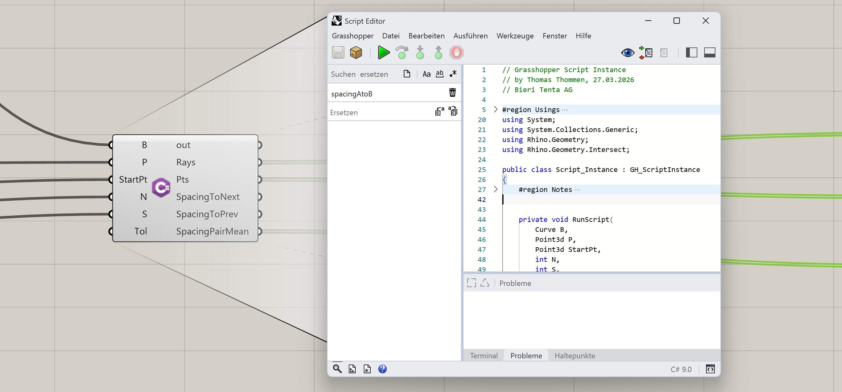
Why a C# component made sense
At the same time, the core of the method is not visual modelling alone. It depends on a repeated sequence of geometric operations and weighted distribution logic. For that reason, implementing the essential algorithm in a C# component within Grasshopper proved to be a sensible choice.
This allowed the logic to remain compact, explicit, and repeatable while still being embedded in a visual parametric model. In this context, C# is not a matter of software preference, but of methodological clarity. Once the task goes beyond drawing geometry and enters the realm of controlled evaluation, iteration, and distribution, a scripted component often provides a more robust and transparent structure than a purely visual definition.
Helper geometry versus actual cutting lines
This distinction is crucial.
The radial lines generated in the parametric model are not the final cutting lines. They are a preparatory construction used to organise the surface and define a coherent sequence of control points. The actual cutting lines are generated later within the 3D FEM and patterning workflow, where they are typically defined as geodesic lines, or in some cases as lines derived through sectional operations on the surface.
This means that the parametric step does not replace cutting-pattern generation. Instead, it strengthens the process upstream. It ensures that the later definition of seams, strips, and flattened patterns is based on a geometrically meaningful and fabrication-aware order.
What this project reveals
The Rapperswil project illustrates a broader point. In textile architecture, the transition from free geometry to fabrication logic is not automatic. Especially in replacement projects, where geometry must be reconstructed and adapted, it is not enough to recover the shape alone. One must also recover, or newly define, the internal order of the system.
In this case, that order is radial. It is linked to the membrane’s geometry, to the orthotropic behaviour of the material, to the narrow width of the available foil, and to the requirements of an economical cutting strategy. The parametric helper geometry became valuable precisely because it made this order explicit and operable.
Conclusion
The replacement of the funnel-shaped canopy at Rapperswil Castle shows that radial panel layouts are not an abstract geometric topic. They are a practical issue of constructability, fabrication economy, and digital reproducibility.
For a membrane of 455 m², rising 12 m high and fabricated from material only 1.4 m wide, intuitive subdivision is no longer sufficient. What is required is a workflow that connects reconstructed geometry, radial material logic, parametric control, and the later generation of actual cutting patterns.
In that sense, the project is less about a single tool than about a design attitude: treating the space between form and fabrication as a discipline in its own right. That intermediate zone, where geometry becomes process, is, in my view, one of the most relevant fields for the further development of digital textile architecture.