RF Welding – the key to dependable details
Abstract
RF welding reliably joins technical textiles and films—provided a few key variables are managed deliberately. For design and fabrication, current, time and pressure matter most, in concert with effective tool width and solid contact conditions. With this logic in mind, settings can be transferred safely from one seam width to another, risks can be identified early, and details can be specified with confidence.
Why seam details determine execution quality
In textile architecture, a seam does more than connect two panels. It contributes to the load path, shapes the appearance, and must perform throughout the service life. Execution planning defines widths and joining sequences; in the workshop these intentions meet real materials, real tools and real environments. Because material testing is often limited early on, teams rely on experience and guidance documents. That’s fine—so long as it remains clear why a value works and when it needs adjustment. A sober look at the process helps.
Responsibility in planning – enabling quality together
“ That’s the fabricator’s job ” is still heard too often. It’s not entirely wrong, but it is incomplete. In RF welding, design and fabrication are two sides of the same coin. Those who draw the details set the conditions in which quality can emerge: seam geometries, tolerances, acceptable ranges, material pairings and sequences. This responsibility does not mean planners should be able to weld; it means understanding the governing variables that make production reliable: current, time, pressure—plus effective tool width and contact quality.
Responsible execution planning treats details as tolerance-friendly, allows small early trials, and defines clear hand-offs: approval is not just a sample, but also a short parameter card (set and measured current, time, pressure, tool type, effective width, visual and quick mechanical check). Where possible, a lean data log with a few fields per run helps. The result is a shared frame of reference—traceable, reproducible and stable across the project.
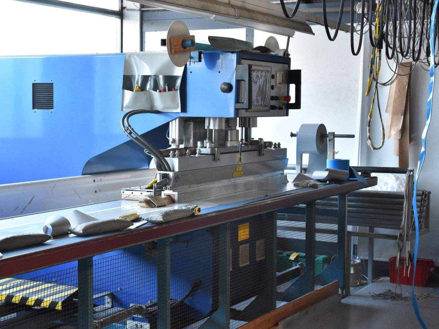
What actually happens in the process
The machine couples a high-frequency field into the seam package. Current heats the polymer layers until they become plastic and bond under pressure. Duration sets the total heat introduced; pressure ensures area contact, expels air gaps, and stabilises the seam during cooling. Tool geometry—especially effective width and the true contact area of textured electrodes—determines how concentrated and how even the heating is. Over-aggressive, locally concentrated heating favours flashover and edge build-up; too little energy or poor contact produces “cold” seams with low strength.
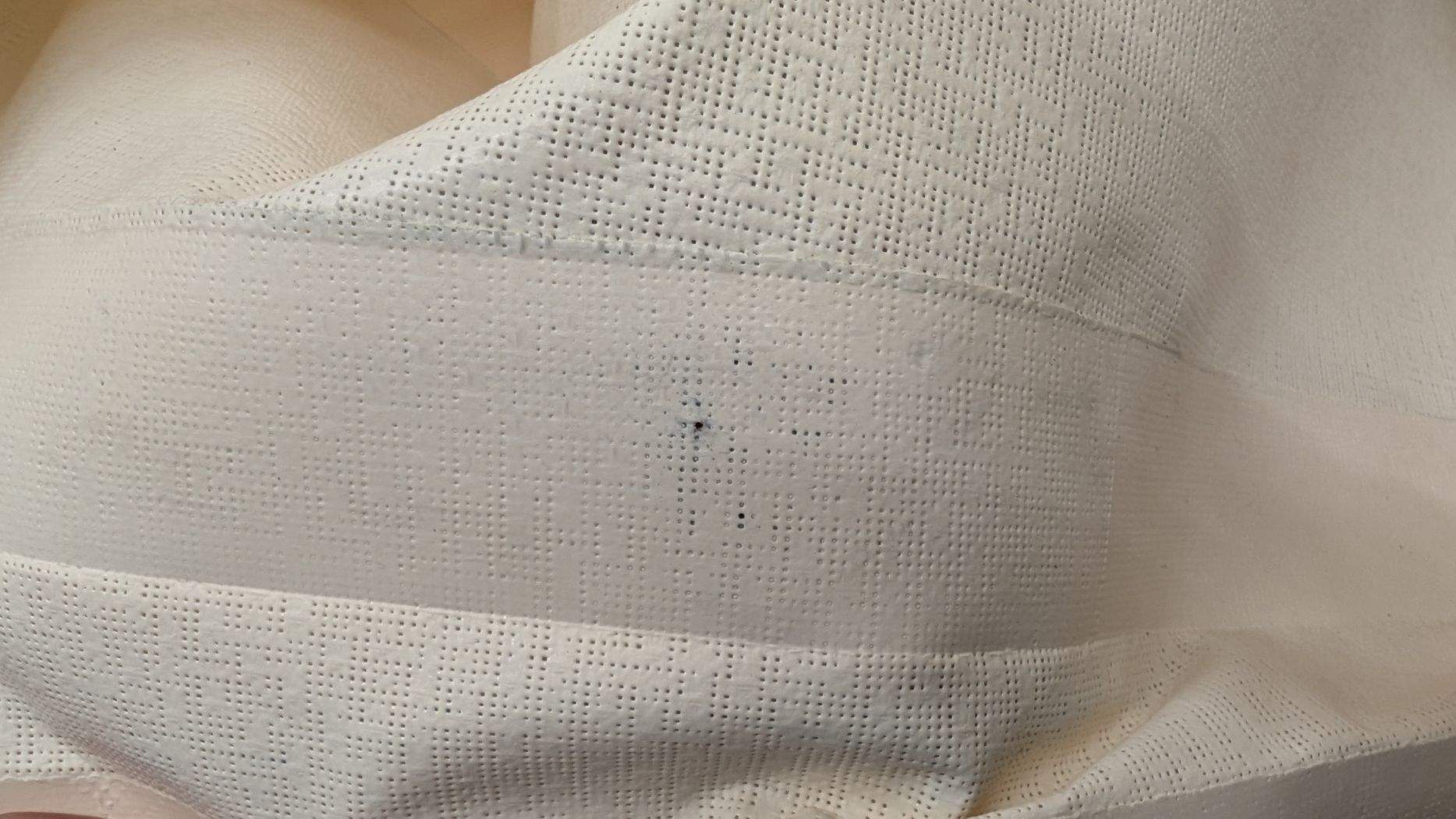
Flashover damage in an RF-welded seam: a localised arc has burned a black crater through the overlap, indicating excessive field concentration or poor contact conditions.
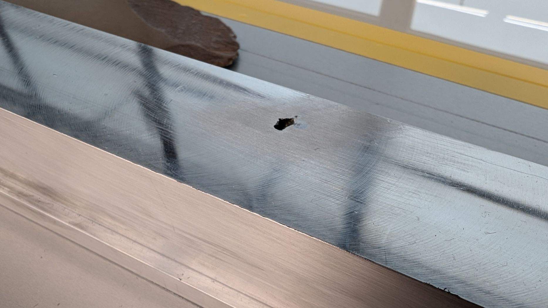
Flashover damage on an RF-welding electrode: a localised arc has left a distinct crater in the tool surface, pointing to field concentration or inadequate contact/earthing.
Parameters and indicators at a glance (concise, no formulae)
Current (anode current): The lever for heating intensity. Higher current heats faster but raises flashover risk if contact is poor. When changing width, adjust with care and periodically verify against the actual measured current.
Weld time: The duration of energy input. Extend when current cannot be raised for stability; shorten if edge build-up/overheating appears.
Pressure: The HMI shows cylinder pressure (not seam pressure). It secures planarity and area contact, reducing air gaps and hot spots. For large contact areas, increase the HMI setting moderately.
Delay (press-delay): A brief pause between closing and heating so the package can settle and contact stabilises.
Cooling time: Hold under pressure after heating; prevents seam opening and calms the surface. Increase slightly with longer heating.
Tool width: The effective electrode width; it governs how heating is “spread” across the seam. With greater width, carry current and/or time accordingly.
Tool length: Affects total contact area and machine load; locally less decisive than width, but important for takt and per-cycle heat.
Tool surface/edge: Flat, ribbed, diamond/waffle, “hook-and-loop”; edge radius and polish shape contact and field peaks. Smooth, lightly rounded edges reduce flashover risk.
Support/barrier: Supports contact (vital for meshes); a thin barrier film can smooth critical spots. Both influence heating effectiveness.
Topcoat/material condition: Acrylic in the seam zone can hinder fusion; weldable PVDF is usually fine but may need slightly more time. Clean, dry interfaces are essential.
Heating-rate proxy: A practical read on heating speed per width. High = fast and potentially “sharper” edges; low = calmer but with cold-seam risk. Keep it as constant as possible for a comparable edge appearance.
EDI (line-based comparison value): An operational indicator of energy per seam length (think “current and time in proportion to width”). The standard way to scale settings safely when changing width.
Areal heating proxy: “Current times time” referenced to effective contact area (width × length). Compares different tool footprints (spot vs long bar) and complements EDI.
Energy proxy: “Current times time” without geometry. Useful when the tool geometry is unchanged and only the machine is driven “softer/harder”.
Mapping per cent power → ampere: The relationship between HMI % and measured current. Per cent is not a reliable stand-in; verify and document the mapping regularly.
Quality indicators (process-proximate): OK rate, flashover rate, short peel/shear checks and visual assessment. Run with small tolerance bands for current, time, pressure and the preferred indicator (often EDI) as an SPC window to pick up drifts early.
How to transfer settings safely – a workshop example
A 40-millimetre overlap seam runs stably: calm edges, clean checks, content operators. The project now calls for 60 millimetres. The naïve option is to keep the same values and hope. The better strategy is to avoid “diluting” the heating and to accompany the change deliberately. In practice that means adjusting time or current so that the heating per seam length remains comparable—or moderating both. Keeping an eye on heating intensity helps you achieve a similar edge appearance, avoid flashover and maintain strength at the original level. Two quick coupons confirm the result, then production can proceed.
Common misconceptions—briefly corrected
The pressure shown on the HMI is the pneumatic cylinder pressure, not the seam pressure. With a larger seam area the same force is distributed across more surface; the actual contact pressure drops. For long or wide tools it is worth scrutinising planarity and, if necessary, raising the regulator value modestly. Equally important: per-cent power is not a reliable surrogate for the actual current in the workpiece. Good shops routinely check whether set per-cent power and the measured current still align—not to be theoretical, but to remain reproducible.
Quality and safety in everyday work
Before a production run, a five-minute check is enough: a clean, dry seam zone; a suitable support; polished edges without burrs; a stable compressed-air supply. Two quick coupons—one visual, one short mechanical check—provide confidence. A daily flashover-safety test should be routine: with the machine powered and idle, trigger the device at the electrode and at the earth foot; it must react immediately. These small rituals prevent big surprises.
Material and tool specifics to keep in view
Acrylic topcoats in the seam area can hinder fusion; where sensible, keep the seam zone free. Weldable PVDF topcoats are usually unproblematic, sometimes needing a little more time. Meshes benefit from a supportive underlay and secure area contact so heating does not “fall through”. Films appreciate gentler heating intensity, softer tool edges and sufficient cooling under pressure so the seam does not reopen on release. None of this changes the basic logic—it simply points to where to act first: contact and edge, then force, then energy.
Conclusion
RF welding is not a mystery. If you consider current, time and pressure in relation to effective tool width and clean contact conditions, you control most of what matters. That makes specifications more robust, conversations with fabricators more concrete, and production more predictable. If you’d like to validate a detail in advance or transfer settings with confidence, I’m happy to outline a lean test series with evaluation—pragmatic, targeted and tailored to your task.